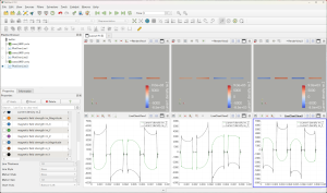
フラット型スピーカーケーブルの電流密度 ― 2022年10月20日 20:19
導体の片端に正負の電圧を加え、反対側を接地しています。
導体抵抗、インダクタンス、表皮効果、近接効果などが複合したときの電流分布となります。
単純に考えて、抵抗性電流(re)が大きい方が良いので、一番右(行き→戻り→行き→戻り)が最も良さそうです。
フラット形状の導体では、近接効果が強く出るようです。
パソコン用スピーカー用ケーブルなど短い場合は、工夫すれば作れる気がします。
ピュアオーディオ用では、ケーブルが長くなるのと要求水準が高くなるので設計が難しそうです(導体を離すとインダクタンスが増えるし、近づけると近接効果が出る)。
Using the Finnish CAE software ElmerFEM, I calculated the current density at 20 kHz for a flat shaped speaker cable.
Positive and negative voltage is applied to one end of the conductor and the other end is grounded.
This is the current distribution when the conductor resistance, inductance, skin effect, and proximity effect are combined.
Simply put, the higher the resistive current (re), the better, so the rightmost (going → returning → going → returning) seems to be the best.
With flat shaped conductors, the proximity effect seems to be stronger.
In the case of short cables, such as speaker cables for PCs, I feel that they can be made with some ingenuity.
For pure audio cables, it seems to be difficult to design because the cables are longer and the requirements are higher (inductance increases when the conductors are separated, and the proximity effect occurs when they are closer to each other).
手持ちの材料でスピーカーケーブルを自作しました ― 2022年10月20日 20:48
デジタルアンプはフルブリッジ回路でスピーカー出力端子(赤黒)の中間がほぼ接地電位になるようです。
(1) 同軸ケーブル(3C-FVR)
編組線に電流を流すと音が悪そうなので、2本用いてφ0.65mmの中心導体で往復させた(シールドに電流を流さないので、磁界はシールドの外に漏れます)。
2本のケーブルのシールドは、スピーカー側で接続し、PVCシースに電圧が加わらないようにした。
試聴結果:
音が明るい気がするが、細かい音まで聴こえる。左右の位相差がよくわかる。
導体を太くすれば、バランスが良くなると思われる。
(2) フラット型スピーカーケーブル
行き、戻り、行き、戻りの2ペア(ElmerFEMの結果から良いと思われる配線方法)。
導体断面積はφ0.8mm相当。
試聴結果:
高音のバランスが良くなったが、音がにじみ位相がはっきりしない。
ぼけて楽器の分離が悪い。
今後は、行き・戻り1ペアのケーブルのみ考えます。
2.5D2V(φ0.8mm) 、S5CFB(φ1.05mm)、5D2V(φ1.4mm)を発注したので、後日のブログで報告します。
I made the following two types of cables and auditioned them from a small speaker from a PC via a digital amplifier.
The digital amplifier seems to be a full bridge circuit and the middle of the speaker output terminals (red and black) are almost at ground potential.
(1) Coaxial cable (3C-FVR)
Since it seems to sound bad if current is applied to the braided wire, two cables were used and reciprocated with a φ0.65mm center conductor (since no current is applied to the shield, the magnetic field leaks out of the shield).
The shields of the two cables were connected at the speaker side so that no voltage is applied to the PVC sheath.
Listening results:.
The sound seems bright, but I can hear every detail. The phase difference between left and right is clearly audible.
The balance would be better if the conductor is thicker.
(2) Flat type speaker cable
Two pairs of cables, one going, one returning, and the other going and returning (wiring method considered good based on ElmerFEM results).
The conductor cross-sectional area is equivalent to φ0.8mm.
Listening results:.
The balance of treble was improved, but the sound was blurred and the phase was not clear.
The sound was blurred and the separation of instruments was poor.
From now on, we will consider only one pair of cables for going and returning.
I have ordered 2.5D2V (φ0.8mm), S5CFB (φ1.05mm), and 5D2V (φ1.4mm) and will report in a later blog.


最近のコメント