LTspiceにより微分方程式を解きました ― 2023年10月15日 14:22
自己流スピーカーケーブルの設計方法 ― 2022年11月06日 19:41
(1) 絶縁体による色付けがある(補正が難しい)。
(2) 静電容量を小さくするため、導体間隔を広げるとインダクタンスが大きくなり、波形のなまりとなる(線形なので比較的簡単に補正可能)。
(3) 2ペアにすると音がにじみ、位相がはっきりしない。
(4) ケーブルにある程度の重量が必要。
(5) 非メッキの単線導体が音が良い。
(6) シールドのある同軸ケーブルの中心導体を2本で行き戻りさせた場合(シールドには電流を流さない)、周波数20kHzではシールドによる悪影響が小さい。
設計方法をまとめると次のようになります。
(1) 安価な材料:TV用同軸ケーブルを用いる。シースがあり適度な重さがある。
S-5C-FB:中心導体φ1.05mm、外径φ7.7mm
S-7C-FB:中心導体φ1.5mm、外径φ10.2mm
(2) 発泡ポリエチレン絶縁の同軸ケーブルを使い、PVCシースに電圧が加わらないように2本同軸ケーブルのシールドをリード線により接続する。中心導体間の静電容量は26pF/m程度になる。
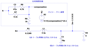
(3) プリアンプとパワーアンプに図の位相補償回路を付けて、インダクタンスの影響を抑制する。
(4) 撚線導体は解析的に答えを得ることが難しく、補正回路を困難にするため除外する。
(5) 表皮効果と近接効果の補正は、インダクタンスと比べて影響が小さい。必要であれば、位相補償回路の次数を上げて対応できるか検討する。但し、磁場の過渡解析が必要なので資金がないと検討できません。
How to design self-made speaker cables
The following is what we have learned from the results of prototyping and auditioning so far.
(1) There is coloration by the insulator (difficult to compensate).
(2) If the conductor spacing is increased to reduce the capacitance, the inductance increases, resulting in a tinny waveform (linear and thus relatively easy to compensate for).
(3) When two pairs are used, the sound blurs and the phase is not clear.
(4) The cable must have a certain amount of mass.
(5) Unplated single-wire conductors sound better.
(6) When two center conductors of a coaxial cable with a shield are used to go back and forth (no current flows through the shield), the adverse effect of the shield is small at a frequency of 20 kHz.
The design method can be summarized as follows
(1) Inexpensive material: TV coaxial cable should be used. It has a sheath and moderate weight.
S-5C-FB: Center conductor φ1.05mm, outer diameter φ7.7mm
S-7C-FB: Center conductor φ1.5mm, outer diameter φ10.2mm
(2) Using a coaxial cable with foamed polyethylene insulation, connect the shields of the two coaxial cables by means of lead wires so that no voltage is applied to the PVC sheath. The capacitance between the center conductors will be about 26 pF/m.
(3) Attach the phase compensation circuit shown in the figure to the preamplifier and power amplifier to suppress the effect of inductance.
(4) Stranded conductors are excluded because they are difficult to answer analytically and make the compensation circuit difficult.
(5) Compensation for skin effect and proximity effect has less influence compared to inductance. If necessary, consider whether it can be handled by increasing the order of the phase compensation circuit. However, since a transient analysis of the magnetic field is required, this cannot be considered without funds.
スピーカーケーブルの位相補償回路の効果 ― 2022年10月23日 20:28
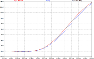
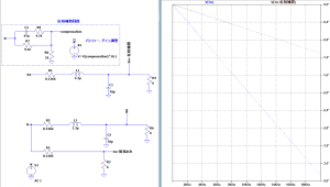
位相遅れが約1/3になっているので、その比率で理想状態に近づいています。
セパレートアンプ(あるいはプリ、パワーアンプの分離機能付き)であれば、ケーブルのインダクタンスの影響を補正できそうです。
This is the effect of the compensation circuit I mentioned earlier.
The phase delay has been reduced by about 1/3, so we are approaching the ideal state by that ratio.
A separate amplifier (or one with separate pre and power amps) would likely compensate for the effect of cable inductance.
スピーカーケーブルの位相補償回路 ― 2022年10月23日 20:20
プリアンプとパワーアンプ間を細工して、スピーカーケーブルへの入力を進み補償しました。
補償の精度が落ちますが、高周波でのゲインが高くなりすぎると危険ですので、コンデンサと直列に抵抗を接続しました。
パラメータを完全に詰めていませんが、約1/3の位相遅れになりました。
The phase delay due to speaker cable inductance is linear and can be compensated for with a simple circuit.
The input to the speaker cable was progressively compensated by modifying the connection between the preamplifier and the power amplifier.
Although the accuracy of the compensation is reduced, I connected a resistor in series with the capacitor because it is dangerous if the gain becomes too high at high frequencies.
Although the parameters were not fully worked out, the phase delay was reduced by about 1/3.
スピーカーケーブルのインダクタンスの影響(2) ― 2022年10月23日 17:40
音源は、ハープです。
位相遅れは定常状態では問題になりません。
しかし、過渡的に変化する音楽信号では、波形の立ち上がり部分でなまりとして現れます。
次は位相補償で改善されるか、検討してみます。
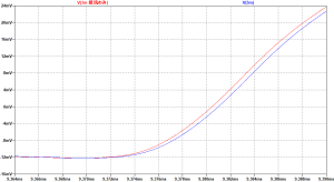
I calculated how the phase delay affects the actual music signal waveform.
The sound source is a harp.
The phase delay is not a problem in a steady state.
However, in a transiently changing music signal, it appears as an accent at the rising edge of the waveform.
Next, we will examine whether phase compensation improves this problem.
最近のコメント